Thursday, May 31, 2012

Dust Control System Footprint

Inlet Pressure Gauge
A fast growing Philadelphia based recycle/recovery center had just opened a new building in northern Delaware.
 Orchem had engineered and built a dust control system for the recycling center in Philadelphia that worked to perfection. It not only kept dust from drifting towards the neighbors when the "C & D" (construction & demolition) was being dumped, it also created a much safer and cooler work environment for the workers.
It worked so well in the current location they wanted to install one at the new facility, however the new building was 3 times larger than old one.
All off- loading of the C & D was to be done inside the plant which would create enormous dust clouds and a very difficult work space. The heavy equipment would be driving back and forth all day kicking up constant dust plumes.
Orchem designed a system that would be able to control dust so the workers could actually work inside. There is also a fine line between controlling dust and creating a giant, slippery mud puddle.
Utilizing very specific flow nozzles, set an exact distance apart, and with the proper pressure we can control all dust in the area.
The unit also had to be designed to control dust in 3 zones so there had to be a 3 zone manifold on the discharge of the pump to direct dust control only to the areas where it was needed.
I applaud the owners of this company. Since there is no concern with dust drifting off site to the neighbors, their only concern was for the workers inside the building. Safety and a good work atmosphere was first and foremost in their minds.
The complete dust control unit comes with;
Pressure switch for low water cut off
High flow pump coupled to a TEFC Baldor motor on a common base
2, 10 micron inlet cartridge filters
Inlet pressure gauge
Discharge pressure gauge
3 zone manifold with high pressure ball valves
Unloader/bypass valve
Control panel mounted in a NEMA 4x enclosure
Timer
Hand/auto/off switch
All associated piping and wiring, high pressure hydraulic hoses, fittings, tees, elbows, and nozzles.
Dust Control System Pumping Unit
Inlet and dual cartridge filters


Pressure switch for low water cut off
Control Panel, NEMA 4X, Timer
Unloader/Bypass valve with pressure gauge


A North Carolina "Waste to Energy" facility that burns everything from tires to refrigerators was having serious issues with build up on the fireside of the boiler tubes. The "klinkers" or build up was retarding heat transfer and causing under deposit corrosion. The other issue was the cleaning of the tubes. Costly and a safety concern for those involved. There is also a substantial revenue loss since the plant has to shut down for maintenance and repairs.
An Eastern North Carolina "waste to energy" plant was having very similar concerns and they had installed 2 high temperature fireside injection quill with outstanding results, so this plant had decided to follow the same path.

 The high temperature fireside injection quill had to be built on site since the application point had to be determined. Our mechanics traveled to the plant, discerned the proper location, built the quill, and oversaw the implementation.
This had to be accomplished in a small window during a plant outage.
The plant was apprehensive about taking pictures of the actual installation which I certainly understand.
The pictures are of the high temperature quill after it was welded.
This is a "Dual Quill Assembly" which means the cooling air is on the outside of the inner quill.
Air Inlet
 Materials of construction are rated for very high temperature.
A small investment to save thousands on down time!

36" High temperature fireside injection quill
Air/Product outlet
Product/Air Inlet
Mounting Flange


Friday, May 25, 2012

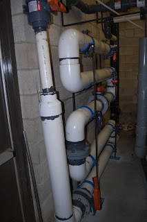
A Philadelphia meat processing facility was experiencing an issue in their waste treatment plant.
The DAF was located to close to their waste stream so the polymer didn't have enough reaction time to activate with the waste. The plant effluent was above the acceptable EPA designated limits. This spelled substantial fines for the company if it was not brought under control.
We were asked to engineer, fabricate and install a retention manifold that would allow the polymer greater contact time with the waste stream. Orchem also had to facilitate a turbulent flow to ensure greater contact time. There was of course a small footprint that had to be taken into consideration.
The existing line was 3" PVC. Orchem had to tie into that line and increase the diameter to 6" to accommodate the required flow/contact time.
The customer also wanted several sample ports for testing at specific locations throughout the retention manifold along with a flush out at the bottom of the manifold.
Based on flow calculations it was determined that a 5 pass manifold with 2 butterfly valves (one at the beginning of the run and one in the middle) would give the proper mixing and contact time. The retention manifold also needed to be valved to be taken out of service if required.
Success.
The following are pictures and descriptions of the waste water retention manifold installed in the customers waste treatment plant 
Looking down at the manifold
Side view. Against the wall. Small footprint.


Tie in from 3" to 6" with isolation valve

Tie in to DAF with isolation valves
2 of the 5 sample ports
Center butterfly valve
Mounted flush to the wall for an open walkway
Bolted to the floor


 Results were outstanding at a minimal cost.