Tuesday, August 21, 2012

A major paper mill located in Virginia was updating and revamping their power plant as well as adding a new boiler and associated equipment.
The current sampling panel was not working properly, in fact it had never worked properly due to insufficient flow through the sample coolers.
While all this construction was going on the paper mill decided to upgrade the existing sample cooler panels as well as install the proper ones for the new plant.
The samples to be cooled were from the high pressure boilers, feed water, condensate, superheaters, and steam lines.
Some of the tests were for Silica, Dissolved Oxygen, and all other related tests for the water treatment.
We designed panels with multiple sample coolers on each panel.
Each sample cooler panel had a common inlet and discharge for the cooling water.

Panel showing common inlet and discharge


Each sample cooler was constructed with Stainless Steel internals and externals. Each cooling coil had 20' of Stainless Steel tubing and each shell was extended for a greater cooling area.
Stainless steel sample cooler internals


Discharge showing stainless steel braided hose to header


Each sample cooler was valved to be independent with valves, and each connection was attached utilizing Stainless braided hose with Teflon internals and/or Stainless steel unions.
Space was a concern so the coolers were staggered on the panel for a smaller footprint.


Inlet with valves and stainless steel braided hose


This accommodated the site requirements for size without restricting the cooling capacity of the sample coolers.
The Stainless Steel drip pan at the bottom of the panel will be used to catch and send to drain all samples not actually being used in the process.
Stainless steel drip pan
Top view of the sample cooler panel

Here are the panels to be put in place for the new facility as well as the upgrade of the existing sample cooler panel.

C&D Dust Control System

A Delaware Construction, Demolition (C&D) transfer station was experiencing extreme dust issues while dumping, moving, and reloading the C&D waste. Not only was it leaving the building to surrounding areas it was also a hazardous work environment for the employees working in the building.
The catch is that the dust has to be knocked down without soaking the floor.
We designed a system that would do just that.
By using nozzles set on specific centers and a regulated pressure we were able to obtain just the right droplet size.
The system also has the capacity to be expanded as the C&D waste intake becomes greater.
The current unit has the ability to operate 3 zones. One at a time, or all three together.
A side advantage is that during the sweltering summer months the building temperature actually drops about 10 degrees which is an added bonus for the workers.
Bottom line is; Happier employees due to better work conditions, higher productivity, and happy neighbors.
Inlet Water Filters

This particular building is 400' long x 100' deep x 50' high

The inlet water for the dust control system passes through 2- 10 micron filters before it reached the pump. This extends pump life and protects the nozzles.

Building view with overhead nozzles


The control panel is wired into a low water cut off valve so if there is a water loss for any reason the dust control pump shuts down.
3 Zone Manifold

Low Water Cut Off Switch


Full Nozzle Flow @ 500 PSI


Nozzles on 5' Centers

Thursday, May 31, 2012

Dust Control System Footprint

Inlet Pressure Gauge
A fast growing Philadelphia based recycle/recovery center had just opened a new building in northern Delaware.
 Orchem had engineered and built a dust control system for the recycling center in Philadelphia that worked to perfection. It not only kept dust from drifting towards the neighbors when the "C & D" (construction & demolition) was being dumped, it also created a much safer and cooler work environment for the workers.
It worked so well in the current location they wanted to install one at the new facility, however the new building was 3 times larger than old one.
All off- loading of the C & D was to be done inside the plant which would create enormous dust clouds and a very difficult work space. The heavy equipment would be driving back and forth all day kicking up constant dust plumes.
Orchem designed a system that would be able to control dust so the workers could actually work inside. There is also a fine line between controlling dust and creating a giant, slippery mud puddle.
Utilizing very specific flow nozzles, set an exact distance apart, and with the proper pressure we can control all dust in the area.
The unit also had to be designed to control dust in 3 zones so there had to be a 3 zone manifold on the discharge of the pump to direct dust control only to the areas where it was needed.
I applaud the owners of this company. Since there is no concern with dust drifting off site to the neighbors, their only concern was for the workers inside the building. Safety and a good work atmosphere was first and foremost in their minds.
The complete dust control unit comes with;
Pressure switch for low water cut off
High flow pump coupled to a TEFC Baldor motor on a common base
2, 10 micron inlet cartridge filters
Inlet pressure gauge
Discharge pressure gauge
3 zone manifold with high pressure ball valves
Unloader/bypass valve
Control panel mounted in a NEMA 4x enclosure
Timer
Hand/auto/off switch
All associated piping and wiring, high pressure hydraulic hoses, fittings, tees, elbows, and nozzles.
Dust Control System Pumping Unit
Inlet and dual cartridge filters


Pressure switch for low water cut off
Control Panel, NEMA 4X, Timer
Unloader/Bypass valve with pressure gauge


A North Carolina "Waste to Energy" facility that burns everything from tires to refrigerators was having serious issues with build up on the fireside of the boiler tubes. The "klinkers" or build up was retarding heat transfer and causing under deposit corrosion. The other issue was the cleaning of the tubes. Costly and a safety concern for those involved. There is also a substantial revenue loss since the plant has to shut down for maintenance and repairs.
An Eastern North Carolina "waste to energy" plant was having very similar concerns and they had installed 2 high temperature fireside injection quill with outstanding results, so this plant had decided to follow the same path.

 The high temperature fireside injection quill had to be built on site since the application point had to be determined. Our mechanics traveled to the plant, discerned the proper location, built the quill, and oversaw the implementation.
This had to be accomplished in a small window during a plant outage.
The plant was apprehensive about taking pictures of the actual installation which I certainly understand.
The pictures are of the high temperature quill after it was welded.
This is a "Dual Quill Assembly" which means the cooling air is on the outside of the inner quill.
Air Inlet
 Materials of construction are rated for very high temperature.
A small investment to save thousands on down time!

36" High temperature fireside injection quill
Air/Product outlet
Product/Air Inlet
Mounting Flange


Friday, May 25, 2012

A Philadelphia meat processing facility was experiencing an issue in their waste treatment plant.
The DAF was located to close to their waste stream so the polymer didn't have enough reaction time to activate with the waste. The plant effluent was above the acceptable EPA designated limits. This spelled substantial fines for the company if it was not brought under control.
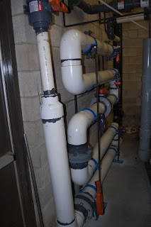
We were asked to engineer, fabricate and install a retention manifold that would allow the polymer greater contact time with the waste stream. Orchem also had to facilitate a turbulent flow to ensure greater contact time. There was of course a small footprint that had to be taken into consideration.
The existing line was 3" PVC. Orchem had to tie into that line and increase the diameter to 6" to accommodate the required flow/contact time.
The customer also wanted several sample ports for testing at specific locations throughout the retention manifold along with a flush out at the bottom of the manifold.
Based on flow calculations it was determined that a 5 pass manifold with 2 butterfly valves (one at the beginning of the run and one in the middle) would give the proper mixing and contact time. The retention manifold also needed to be valved to be taken out of service if required.
Success.
The following are pictures and descriptions of the waste water retention manifold installed in the customers waste treatment plant 
Looking down at the manifold
Side view. Against the wall. Small footprint.


Tie in from 3" to 6" with isolation valve

Tie in to DAF with isolation valves
2 of the 5 sample ports
Center butterfly valve
Mounted flush to the wall for an open walkway
Bolted to the floor


 Results were outstanding at a minimal cost.


Friday, January 27, 2012

Dissolved Oxygen Monitor and Filter Skid

A New York power generating station needed to monitor the Dissolved Oxygen content of the boiler feedwater. They had two necessary collection points, however only wanted one dissolved oxygen monitor.
The customer also wanted both samples filtered before it entered the D O Monitor. This would produce more accurate readings as well as protect the device
.
Waltron Dissolved Oxygen Monitor

Dual Cartridge Filter System, Stainless Steel Tubing


Orchem Pumps designed and manufactured the skid to the customers specifications.
We used a Waltron Dissolved Oxygen Monitor.


Components mounted on "U" channel
Pre wired


The unit was pre-piped using 1/4", 316 Stainless Steel tubing, and connected with Parker compression fittings. Flow would be regulated from each collection point to the individual cartridge filters using Parker Stainless Steel needle valves. This would ensure precise flow to the Waltron Dissolved Oxygen sensor.

The complete package was delivered and installed on the discharge side of their sample coolers.

Compact design

The unit is compact and the customer wanted it floor mounted instead of wall mounted. Either option was available. The components were mounted on "U" channel so if other controllers needed to be added in the future it would be a simple addition.

Wednesday, January 18, 2012

Stainless Steel Boiler Water Sample Cooler

A Southeast chemical manufacturer was using softened water as the cooling medium to cool their boiler water sample. That required a stainless steel shell due to the corrosive nature of the softened water. They were doing this to recover the heat from cooling the sample and sending it directly back to the deaerator.
Stainless Steel Shell and coil with coupling


Stainless Steel coil and top going into the shell


 By using this procedure they required less energy to heat the water since it had already picked up heat in the cooling process.
3" schedule 40 Stainless Steel Shell with over 20' of SS coil


The chemical company also needed a removable coil for repair or replacement if necessary. They also recognized the advantage of having a removable cooling coil if they needed to sample water in a remote location.
We provided a Model RRSS water cooling sampler that fit all their needs.

Wednesday, January 11, 2012

Odor Exchanger for Stack Odor Control

One of the worlds largest food processing companies was having issues with a waste water collection tank that was"burping" odors as more of the waste water slurry was added to it. (This particular facility is in the Mid-Atlantic region.)  The surrounding community was raising concerns regarding the steady odors escaping from the tank.

The processed waste was eventually going to be "land applied" so there could be no additional chemicals added to it to reduce the fugitive odors.

The solution for odor abatement had to be immediate and all natural.
Stack In Line Odor Exchanger

Orchem developed the Odor Exchanger to be used specifically for this type of stack odor control.

The unit is compact, easy to install, and the all natural odor control media inside is replaceable.

All Natural Carbon Filter Media
Internal Distribution Plate

Inlet Cap
This particular "Stack Odor Exchanger" is made of PVC and has male pipe thread connections. 2" inlet and 1" discharge.

One of the advantages of the Odor Exchanger for stacks is that it can be designed for almost any flow range, with any material of construction, and with any connections to make it compatible for your particular odor control application.

Just think!
Happy neighbors. All natural. Easy to install. Inexpensive, and no operating cost.
How often does that happen?

High Temperature Fire Side Injection Quill

A Southeast, "wood to energy" facility was experiencing long and drawn out turn around time on their shut downs and general maintenance schedule due to the substantial build up on the outside heat exchange surfaces of the boiler tubes. The slag would have to be dynamited off which is costly and dangerous.
The chemical supplier developed a product, however feeding it into an 1800 degree chamber proved to be another issue.
High Temperature Fireside Injection Quill


We developed the High Temperature Fire Side Injection Quill which would allow the product to be fed, and we utilized air to cool the product and the quill at the same time. This kept the additive from flashing prior to being delivered into the fire box.


Inner Shell, Outer Shell Injection Points


The High Temperature Fire Side Injection Quill has an inner and outer shell for cooling and to facilitate a more dynamic delivery system.
Cooling Air Injection Point for the Outer Shell


The result was a dramatic reduction in down time and it eliminated the need for blasting the deposits off the tubes.
This improved safety and productivity for the facility.
All alloys used in the development of this high temperature quill were specifically selected for this application.

Monday, January 2, 2012

Water Cooling Sampler With Removable Coil.

Many industrial operations utilize water for cooling that has a high degree of foulants or contaminants which can coat the outside of a cooling coil. When this happens the heat transfer is drastically reduced and it takes longer to draw a representative sample. There are 2 options;
Unit shown with 3" shell, 18" long

1- Throw the sample cooler away and purchase a new one, or
2- Purchase a cooler that has a removable coil so it can be cleaned.
Obviously, the removable coil is the better choice.
The Model RR Sample Cooler has a 316 stainless steel coil and it is held in place using a victaulic coupling for easy removal and cleaning.
Most customers find it beneficial to keep an extra coil on hand so they can continue sampling, boilers, condensate, feedwater, or process water while one is being cleaned.
Removal and installation of the new coil takes about 5 minutes. There are only 2 nuts on the coupling.
Take them off, pull the old coil out, put the new one in, re-attach the coupling and you're back up and testing your water again.
Coil, Shell, and Coupling

There are options for the materials of construction on the coil and the shell, depending on your particular application.
This particular unit is being shipped to a large plastics manufacturing facility that uses river water to cool the boiler sample in their power plant.

1/4" MNPT Sample in and out. 1/2" FNPT cooling in and out./

These units are inexpensive and a very practical tool in optimizing a treatment program.